- Furnace Safety Supervision System
- Ignition Control System
- The Ignition And Combustion Equipment
- Energy-saving Combustion System
- Combustion Test Bench
- PLC Programmed Control System
- Industrial Television Monitoring System
- Flare System
- Intelligent Online Soot Blowing System
- Acoustic Gas Temperature Measurement System(SEI)
- Compressor Optimization Control System(CCC)
http://www.nendar.com
Phone:0516-83899666
postcode:221008
E-mail:xznengda@126.com
Address:Hardware district 1 11,National University Science Park of China University of Mining and Technology,Xuzhou,Jiangsu,China
Compressor Optimization Control System(CCC)


In a modern iron and steel enterprises, reliable and efficient operation of the blast furnace is a key factor in the success of the entire plant and the potential benefits. Without adequate and reliable supply to the downstream molten steel mills, to meet product supply all important customer contracts will become difficult or even impossible.
Can be seen on the head of a large cold hydraulic control valve (blast furnace vent valve). Generally, by using the blast furnace operator (usually manually) the vent valve to quickly discharge portion or all of the blast furnace to the atmosphere. This vent valve is opened emergency operations applicable to overpressure control or reduction furnace conditions difficult row wind operation. In the latter case, by making the operator of the pressure drop for short sitting material to increase the charge of a desired breathability.
Large centrifugal or axial compressors (turbo fan) are often used to supply cold blast furnace. Sometimes these fan driven by the motor, but more conventional, usually driven by condensing steam turbine, which is usually inexpensive integrated steel production process steam generated to drive. These fans are usually stand-alone mode, or in parallel, or distributed to air manner. Even in stand-alone mode (one machine, one furnace), often still use multi-line configuration for the fan switch in order to increase the flexibility of the process operation.
1.1 Target blower control system
The four main objectives of modern blast furnace blower control system are:
-Enhancement (or maintenance) of the blast furnace and the reliability of turbine fan;
-Maximizing yield of the blast furnace;
-Minimize the amount of steam (power consumption);
-Simplify operation, enhance the degree of automation systems.
By improving turbine fan anti-surge control system can operate effectively expand the scope of the turbine fan, does not require venting operation within this range. A wider range of more efficient operation means during operation of the blast furnace feed sitting, during startup and shutdown, and the need to reduce the amount of other operating phase the air volume of the air discharged to the atmosphere would be reduced. Further, in some cases, due to the change of composition of the charge, the turbine blower is designed with a mismatch in the blast furnace becomes; as a result, even in the normal operation of the blast, and stable continuous venting can not be avoided. By eliminating unnecessary venting operation to save energy and become a very significant way to get the blast furnace operation to maximize efficiency.
2.The unique control scheme control issues / standards
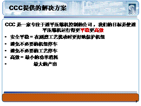
American Compressor Control Company (CCC)-based high-speed digital control hardware dedicated anti-surge control strategies and unit performance, and are usually carried out in a controlled manner to a redundant configuration. By focusing on key services turbomachinery applications, and to achieve the installation of hundreds of similar applications, control strategies and algorithms have been standardized and a fully-site verification.
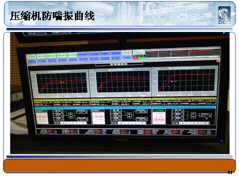
Disturbance blast furnace operation is often called the most challenging emergency break wind, the wind off the emergency incident, due to an error of the operator, the valve failure or because of problems in the process of changing the furnace, cold air is often removed. Hugh wind blast furnace combustion process is not only a huge interference, and cause hanging; while generating enormous pressure shock waves in the cold Explorer. This huge increase in pressure will cause the pipeline upstream of the turbine fan into the surge condition and cause huge fluctuations in the flow of cold air within a few seconds - and further lead to the blast furnace to produce molten iron is too hot and could make a splash into the hot air outlet . Surge caused by the occurrence of reverse thrust and turbine blower temperature rise, driven turbine fan and turbine will cause potential damage. For the unit will result in catastrophic damage to the prolonged shutdown, and, eventually leading steel production interruption.
First, the mass flow controller is required to accurately measure the flow rate supplied to the blast furnace. However, usually the hot air downstream of the stove temperature 1,100 ° C, the temperature limit has been reached the transmitter electronics, usually the hot air can not be measured directly and accurately. Therefore, the measurement must be carried out in the cold line, and the stage of the stove hot air flow must decrease caused during the charge air outlet flow blower net compensation.
CCC performance controller required flow Explorer installed on the cold, pressure and temperature of the analog input signal, used to calculate the mass flow. In one machine, one furnace operation, the output performance of CCC steam turbine controller for adjusting the speed (speed controller speed setpoint) and / or guide vane angle blower. Variable speed and variable geometry (guide vane / vanes) compressor applications, two output controller can be configured to be used with a breakpoint, the degree of process control and limit overlap.
When a filling valve opens, indicating the start of the furnace and the blast furnace charge and traffic began to decline. Filled dampers open to natural causes cold line pressure drop, while the mass flow rate remained relatively unchanged. Once the filling valve is opened, and switches to pressure control, the controller is able to "see" the interference and the pressure begins to increase turbine speed and / or the guide vane to compensate. In many applications, the trend analysis can be seen by the wind during the stove for cold filling pressure control can provide a very smooth and relatively precise control of the mass flow of hot air. When the air filling is completed, the system will switch to the mass flow control, the flow rate of the furnace time for the calculated mass flow rate, and thereafter to smoothly ramp the most recent operator selected set point.
Any time the operator wishes to disable the pressure control mode, the mass flow control mode is selected, and at any time when the blast furnace is operated vent valve opens personnel are typically mass flow control mode (automatic) starts. The pressure control mode can be selected whenever the operator desires stable line pressure (usually sit during operation of the material or during the start or stoppage of the blast furnace).
2.1 The maximum valve opening (MOV) control is applied to give way for the wind
In applications using one or more blowers supply air to a plurality of blast furnaces, the control pressure in the cold air duct is generally independent of the mass flow and sent to each of the blast furnace in the blast. In this case, each individual wind blast furnace by independent flow control valve (usually butterfly) to control. Excessive pressure on the flow control valve means a loss of energy generated and the waste of the system limits the maximum available pressure. Manifold pressure using a dedicated control strategy optimization can significantly reduce the pressure valve on the drop, and improve the operating efficiency of the blast furnace.
In this regard, CCC optimized maximum valve opening degree (MOV) to continuously monitor the control strategy will cold flow control valve of the valve, and automatically adjust the cold air header pressure setpoint control. In addition to the typical mass flow and pressure control requirements in these applications the outer control loop, CCC MOV control strategy of using an additional dedicated control circuit which controls the output flow rate or by using a valve position transmitter, independent of the flow control the valve and the valve position as a high select the process variables, the operator can adjust it to a "location" set point for comparison. MOV as the output of the controller and the main manifold pressure set point controller.
MOV control system operates to maintain the maximum opening degree of the control valve as close to 100% open, while ensuring the controllability of the other flow control valve. This control strategy includes both CCC implementation of all relevant circuit decoupling function, these circuits are designed to maximize system stability and directly regulates the blower throughput (by a rapid perturbation bypass position control to pressure control loop cascade control) to match the highest flow resistance of the blast furnace flow requirements.
To further explain the basic system operation, if the controller setpoint is set MOV 95% open, the control valve when the maximum opening degree to the further opening of the opening degree of 95% or more, MOV controller will begin to increase manifold pressure setting to ensure that all points of the flow set point is satisfied. In other words, when the maximum opening of the valve to move to less than 95% open, MOV controller will reduce the manifold pressure set point to ensure minimal pressure drop in the system. In some installed applications, CCC found that when the pressure set point in increasing moves too fast or too slow to move in the fall, the use of asymmetric loop gain will reap the benefits.
3.System Automation
CCC mass flow controller provides several automatic features:
-Automatic startup and shutdown sequence;
-Online fan automatically load balance during the handover process;
-Material in blast furnace operation to reduce the process to sit automatic air flow;
-When the blast furnace vent valve open automatic mode switching. Current local switch to control the speed or the speed of the pre-selected set point flow control options.